Creating Visual Representations of Biomass Energy Conversion

Biomass easy diagram drawing – Visualizing the process of biomass energy conversion is crucial for understanding its complexities and potential. Clear diagrams can effectively communicate the various stages involved, from the initial biomass feedstock to the final energy output, and highlight the environmental implications. This section provides a step-by-step guide and examples of effective visual representations for various biomass energy conversion methods.
Biomass Power Plant Diagram
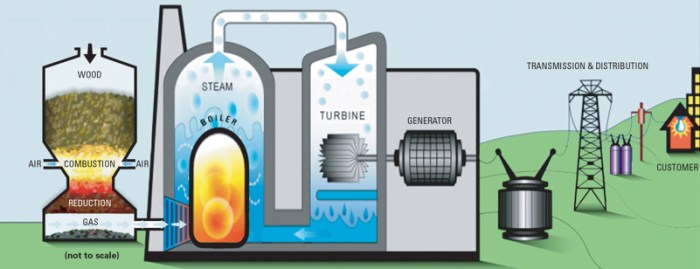
A basic diagram of a biomass power plant should illustrate the key components and the flow of energy. Begin by drawing a large rectangle representing the plant itself. Within this rectangle, depict the main stages: biomass handling (storage, conveying), combustion (boiler), steam turbine, generator, and cooling tower. Use arrows to show the flow of biomass and energy. The biomass enters the plant, is combusted in the boiler to generate steam, which drives a turbine connected to a generator producing electricity.
The spent steam is then cooled in a cooling tower and recycled. Label each component clearly, and use different colors to represent different energy forms (e.g., brown for biomass, red for heat, blue for water, yellow for electricity). Consider adding a smaller rectangle to represent emissions, indicating their release into the atmosphere. This visual representation provides a simplified but comprehensive overview of the process.
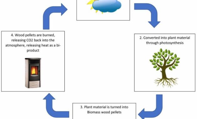
Creating a simple biomass diagram involves illustrating the various sources and their transformations. Understanding cyclical processes, such as the flow of energy within an ecosystem, is key; this is analogous to understanding the complex symbolism within the aztec sunstone drawing easy , where concentric circles represent cosmological cycles. Returning to biomass diagrams, the simplicity of the visual representation allows for a clear understanding of complex biological processes.
Visual Representations of Biomass Gasification, Pyrolysis, and Combustion
Effective visual representations of these processes should highlight the chemical and physical transformations.
Biomass Gasification
Illustrate biomass gasification with a diagram showing biomass feedstock entering a gasifier reactor. Inside the reactor, depict the high-temperature, low-oxygen environment converting the biomass into a syngas mixture (primarily carbon monoxide, hydrogen, and methane). Show the syngas exiting the reactor, potentially going through further cleaning and processing before use in a gas turbine or other applications. The diagram should clearly show the input (biomass), the process (gasification within the reactor), and the output (syngas).
You could use different colored circles or shapes to represent the various components of the syngas.
Biomass Pyrolysis
For biomass pyrolysis, depict a reactor where biomass is heated in the absence of oxygen. Show the three main outputs: bio-oil (liquid), biochar (solid), and syngas (gas). Use distinct containers to represent each product, indicating their different properties and potential uses. Arrows should show the flow of biomass into the reactor and the separate outputs. Consider adding labels highlighting the temperature and pressure conditions within the reactor.
This helps to convey the specific conditions required for pyrolysis to occur.
Biomass Combustion
A simple diagram of biomass combustion shows biomass entering a combustion chamber where it reacts with oxygen at high temperatures, producing heat energy. This heat energy is used to generate steam or directly used for heating. The diagram should show the input (biomass and oxygen), the process (combustion), and the output (heat and combustion byproducts like ash and flue gases).
The flue gases could be depicted leaving the chamber via a chimney, representing emissions. The use of different colors for oxygen and heat energy will further enhance the clarity.
Environmental Impact of Biomass Energy Production, Biomass easy diagram drawing
A diagram illustrating the environmental impact should use a central circle representing biomass energy production. Branching outwards, show both positive and negative impacts. Positive impacts could include reduced greenhouse gas emissions (compared to fossil fuels), carbon sequestration (if sustainably managed), and potential for rural development. Negative impacts could include air and water pollution from combustion byproducts, deforestation and habitat loss (if unsustainable harvesting practices are employed), and potential for soil degradation.
Use different colored arrows to distinguish positive and negative impacts, making it immediately apparent which are beneficial and which are detrimental. The size of the arrows could even be proportional to the magnitude of the impact, further enhancing the visual communication. Adding a key explaining the symbols and colors would enhance understanding.
Illustrating Biomass Composition and Properties: Biomass Easy Diagram Drawing

Unlocking the potential of biomass energy requires a deep understanding of its composition and properties. This section will visually explore the chemical makeup of different biomass types and delve into their energy content and moisture characteristics, crucial factors influencing efficient energy conversion.Biomass, a diverse resource encompassing agricultural residues, forestry byproducts, and dedicated energy crops, possesses a complex chemical structure.
Understanding this structure is key to optimizing its use for energy production.
Biomass Chemical Composition
A visual representation of biomass chemical composition could be a pie chart. Imagine a circle divided into three main segments, representing the major components: cellulose, hemicellulose, and lignin. Cellulose, the most abundant component, might occupy the largest segment, perhaps 40-50% of the total. Hemicellulose would constitute a smaller segment, maybe 20-30%, while lignin, a complex polymer, would make up the remaining portion, approximately 15-30%.
The exact proportions would vary depending on the specific biomass source – wood from hardwood trees would have a different composition than agricultural straw. Each segment could be color-coded for clarity, and labels could indicate the percentage composition of each component. This visual aids in grasping the relative abundance of these crucial components in different biomass types.
Further, smaller segments could represent extractives (e.g., resins, waxes) and ash, acknowledging the presence of minor components.
Biomass Energy Content and Density
A bar graph would effectively illustrate the energy content and density of various biomass sources. The horizontal axis would list different biomass types (e.g., wood chips, corn stover, switchgrass), while the vertical axis would represent energy density (measured in MJ/kg, for example). Each biomass type would be represented by a bar, with its height corresponding to its energy density.
A similar graph could be created to show energy content per unit volume. For example, wood chips might have a higher energy density than straw, but their bulk density might be lower, resulting in a different energy content per unit volume. This visualization immediately compares the energy potential of different feedstocks, aiding in selection for optimal energy production.
For added context, values for common fossil fuels (like coal or natural gas) could be included as a benchmark for comparison.
Biomass Moisture Content and its Impact on Energy Production
| Moisture Content (%) | Impact on Energy Output |
|---|---|
| <10% | Optimal energy output; minimal energy required for drying. |
| 10-20% | Moderate impact; some energy loss due to moisture evaporation; may require pre-drying depending on the technology used. |
| 20-30% | Significant impact; considerable energy loss; pre-drying is generally necessary; efficiency decreases depending on the drying method used. |
| >30% | Substantial energy loss; significant pre-drying is essential; may not be economically feasible without efficient drying processes. Increased risk of equipment damage due to excess moisture. |
High moisture content requires more energy for drying, reducing the net energy output from the biomass. For instance, using wet wood in a combustion system will consume a significant portion of the generated heat to evaporate the water, resulting in lower overall efficiency. Conversely, properly dried biomass leads to more efficient combustion and higher energy yields. This table highlights the importance of pre-treatment and drying in maximizing the energy potential of biomass.
Q&A
What software is best for creating biomass diagrams?
Various software options exist, from simple drawing tools like PowerPoint or Google Drawings to more advanced programs like Adobe Illustrator or specialized diagramming software. The best choice depends on your skill level and the complexity of the diagram.
How can I ensure my biomass diagrams are accurate and scientifically sound?
Consult reputable scientific sources and utilize data from peer-reviewed publications to ensure accuracy. Clearly label all components and processes, and cite data sources within the diagram or accompanying text.
What are some common mistakes to avoid when creating biomass diagrams?
Avoid overly complex diagrams, ensure clear labeling, maintain consistent scaling, and avoid misleading or inaccurate representations of processes or environmental impacts. Oversimplification can be just as problematic as excessive detail.

